
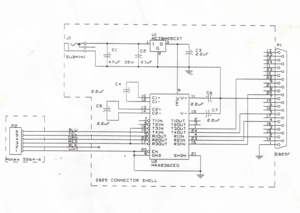
Some versions of this adapter had a "red wire" that was hooked to a pin on the main board of the radio to supply power to the adapter. This version appears to have a jack on it to hook a 'wall-wart' power supply to it.
All device numbers in the schematic are surface mount devices, as the factory unit was mounted inside a 25 pin D-sub shell. It shouldn't be a problem to find devices with the same specs in a standard 'thru-hole' package, if needed.
In order to solve some apparent confusion, the DB25F connector at "P1" in the schematic is for a serial (COM) port, not a parrallel port. A nine-pin plug could be used just as easily as a 25-pin. I will add the correct pin numbers for use with a nine-pin plug if needed.
BTW, this is a 'genuine' Maxon schematic, not an untried knock-off. This is what is actually inside the original Maxon adapter.